
Getting Started with the FV-1:
A first look into DSP
You're maybe wondering how all these pedal compagnies are making crazy complicated effects in a small footprint. The answer is almost always digital processing.
One very popular Digital Signal Processor (DSP) amongst pedal makers is the Spin-Semiconductor's FV-1. It is easy to integrate it into a pedal design and coding was made relatively approachable. There're far more complex DSPs out there, with a lot more option like Analog Device's SHARK DSP used by Strymon, but the FV-1 will be able to handle most guitar effects.
Getting into digital signal processing is not an easy task, especially if you're not used to a digital workflow. The good news is that there's fantastic tools and documents here to help. I made this article to help you put everything together and follow the steps in the right order.
What's a DSP Anyway ?
A Digital Signal Processor is a very specialised microprocessor made for processing signal in real time. In order to do real time processing, the processor must reliably finish all its computing in one clock cycle. This is something generalists microprocessors, like the one in your computer, are not good at. The architechture and set of instructions of a DSP are optimized for speed. Most modules of the architecture are the same that in a regular microprocessor.
You can find DSPs in a lot of audio equipment like digital mixing tables, digital audio interfaces, effects racks and even microphones.
Presentation of the FV-1
Looking at its datasheet you can see that the FV-1 is a fairly small chip in its SOIC-28 package. Here's the FV-1 architecture, let's study it for a bit:

First of all, you can see the FV-1 is stereo and it has converters in it. This mean you can inject a stereo analog signal at the inputs and retrieve an analog stereo signal at the outputs. This is very convenient, that means we don't have to use an external converter chip, unlike a lot of DSPs.
The clock can be generated by a 32 kHz crystal or an external clock up to 48 kHz.Once again this is very easy to implement, just by hooking-up a crystal between two legs. One fun trick is to reduce the clock frequency to introduce a glitchy texture.
There're three potentiometer inputs that can be used to add flexibility to your program. For me, this is one of the setbacks of the FV-1 because sometimes three variable parameters in a program is not enough. However, it's still plenty of possibilities and pedal makers proved it again and again.
The FV-1 comes with 8 factory programs:

However, it becomes interesting when you start programming your own effects. Spin-Semi created a free IDE in which you can do that called SpinAsm (Windows only).
Your programs can be executed by the FV-1 via an EEPROM. You can write 8 programs on an EEPROM and connect it to the DSP. You first need to select EEPROM on the select pin and then you can use the 3 program-select pins to select your program into the EEPROM (by counting in binary).
Here's the typical application schematic from the datasheet:

The power supply is 3.3V, in pedals this is achieved by using a 78L33.
The EEPROM model is a 24LC32A it is designed to work with this specific EEPROM. I managed to switch between two EEPROMs with a DPDT switch like in the Dr. Scientist Bitquest, but the program selection needs to change in order to load the programs from the second EEPROM. I'm not sure how to improve that.
To interface the potentiometers to the FV-1 you just need to divide the 3.3V rail and connect it to the appropriate pin, like shown. You can select the internal programs or the EEPROM programs with a SPST switch. The program number can be selected by three switches making a binary code.
If you want to see the FV-1 in a guitar pedal schematic you can refer to the Molecular Disruptor by David Rolo or the Arachnide by Pedal PCB.
Getting Started
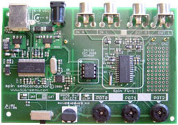
Hardware:
To begin programming for the FV-1 you mainly need a way to put your programs on the EEPROM and a way to send audio to the DSP and listen back. The easiest way is to use a development board, it connects directly to your computer to program the EEPROM and has all the electronics needed to send and listen audio. I have the official development board which is a bit expensive. A cheaper DIY alternative made by Pedal PCB exists and looks very promising.
You could also try with a generic EEPROM programmer and a pedal circuit but debugging your programs will certainly be a hassle.

Software:
You will need a Windows machine with SpinAsm installed.
You can go ahead and download SpinCAD Designer on Github. It is an awsome graphical interface (kind of like Max-MSP) made by Holy City Audio to program the FV-1. To use it you need Java Runtime Environement, then you can just execute the .jar file.
This tool can be used to make programs very quickly and you can better understand programs by studying its output.
One more useful feature, SpinCAD has a simulator. Put a wav file as input and you can directly hear your program on your computer. So technically you don't even need a FV-1 to start programming for it. A way to test your programs for real is still needed but it's a neat feature to test your program without flashing the EEPROM.
Coding for the FV-1
Let's start by listing where you can find knowledge and help. Spin-Semiconductor's site hosts a very complete knowledge base and the support forum where you can find programs, help and discussions on the FV-1. Here's a list of programs put together by MsStratMan. If you lost your program file and want to get it back from your EEPROM here's a decompiler programmed by Igor from Shift Line.
First the big principles. Each clock cycle, the converters produce a new audio sample, also the DSP executes every instruction in its program from top to bottom. What you write in your program is executed in a loop 32768 times a second (if you're using a crystal as clock source). As you'll see later the DSP is optimized so it can do some things at the same time, for example it can read a value and multiply it in a single operation. The maximum length of your program is determined by the speed of your DSP, measured in MIPS (million instructions per second), and your sampling frequency. The FV-1 can do 6 MIPS at 48 kHz.
Registers are memories, the FV-1 has 64 registers. There're 32, 24-bit, user registers that you can use when you want to store an audio sample to route it elsewhere in your code for example. The values of the inputs, outputs and potentiometers are also stored in reserved registers you can access.
You code by using instructions. The FV-1 has 28 different instructions they are explained individually here and here. We will see the most important ones but you should definitely be able to use most of them. Spinsemi wrote a handy cheat-sheet for quick reminders.
One other important thing to know is the accumulator register. You can see it as your work bench, when you read values it goes on the accumulator, then you can transform this value on your workbench end send it to another register. You can also clear your accumulator at any moment.
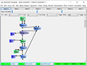
We will see how to code for the FV-1 by studying simple SpinCAD programs. Let's start with a simple volume control. I know, it's not that impressive but we will be able to understand the basics of SpinAsm code with it. You can click on any program to download it and experiment with it yourself.
In SpinCAD it looks like this, four blocks, a volume block connected to the left input and left output, controlled by the first potentiometer.

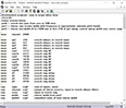
By using File > Copy ASM To Clipboard, we can paste the program into SpinAsm and this is what we get.

As you can see most lines begin with a semi-collumn, these lines are comments and aren't part of the program. SpinCAD automatically uses comments to indicate the program's name and the function of each potentiometer. Also, a comment line is added for each function block used in SpinCAD (here Input, Pot0, Volume and Output). SpinCAD writes every instruction in capitals and adds all zeros after the point, you are not requiered to do that when writing your own code.
The first instruction is "rdax adcl,1". Rdax is used to read a register and put it in the accumulator, in this case we want to read the left input. It can be addressed simply by writing adcl (analog to digital convertor left). This instruction also gives you the opportunity to multiply this value by a number between -2 and +1.9999389 (multiplying by a negative number inverts the phase). Here we multiply it by 1 because we don't want to affect the input gain yet. We also could have used "ldax" which is the same instruction without the multiplication, it also overwrites anything left in accumulator before it.
The next line is "mulx pot0". Mulx is used to multiply the accumulator value by another register, the result will be the new accumulator value. The left input value will be multiplied by the value of pot0. Pot0 is a value between 0 and 1, as you probably guessed this register's value is determined by the voltage at the Pot0 pin. Now the potentiometer value can control the input's volume. We just need to get this signal to the output.
The next line is "wrax reg0,0". The wrax instruction is used to write the accumulator value in a register and then multiply the accumulator value. In this line we put the signal in register 0 and then multiply the accumulator value by zero, effectively clearing it.
The next two lines get the reg0 value back and then output the signal and clear the value of the accumulator with "wrax dacl,0".
So, we made it to the end, but we made some unnecessary operation along the way. We didn't need to write the modulated signal to a register if we intended to write it directly to the output. Here's a more efficient way to write this program with commentaries for each line.

A Simple Tremolo: Using the LFO
Now that you know how the code works let's get into some more advanced programming using the peripherals the FV-1 disposes of. The FV-1 has two sin generators, two ramp generators and a delay memory (1 second of audio at 32 kHz). With these peripherals we can access new territories of effects, like pitch, delay, tremolo, flange, chorus...
To show you how to use them I wrote two simple programs, a tremolo and a delay. Each one will show you how to address some peripherals and introduce new instructions.
Let's start with the Tremolo. We will create a controllable LFO with a sin generator and use it to modulate the audio. Here's the code and it's rough equivalent in SpinCAD.


Let's go through the program together. When using a function generator, you first need to initialize it. You only need to make this once, so the "skp run,1" makes sure the initialization line is executed only once. You can make a lot of clever tricks by skipping lines. "Run" is the condition to fullfil for skipping lines and 1 is the number of lines to skip if the condition is fulfilled.
The instruction for initializing a sin generator is "wlds" followed by the number of the sin generator (0 or 1), its frequency (9bits) and its amplitude (15bits). In our case the last two numbers are of no importance since they will be controlled by two potentiometers.
To control the frequency and amplitude of the LFO we just need to write to the appropriate registers. For the first sin generator they are "sin0_rate" and "sin0_range". So next we write each pot value into these registers. We multiply the rate pot by 0.4 to keep the maximum rate around 16Hz.
Next, we need to put the LFO value in a register multiply by it later. To get an LFO value you can use "cho rdal". Cho is one of the most complicated instruction in the FV-1 set, but "cho rdal" is fairly strait forward.
Now that the LFO value is in the accumulator we need to have it between 0 and 1, not between -1 and 1 like it is by default. We do that by multiplying it by 0.5 and adding an offset of 0.5. We can do exactly that by using the "sof" instruction. The sof instruction is very helpful and can multiply and add by numbers between -2 and 1.9999389. You can use it to build gain stages for example.
Now that the LFO is initialized, controlled by pots, scaled to a desirable range and stored in reg0. All that is left to do is multiply the audio input by reg0 and output the result. That's what the three last lines are for.
A Simple Delay: Using Delay Memory
To demonstrate how to use the delay memory in the FV-1, I coded a very basic delay. Here's the SpinCAD equivalent and the program itself. Once again don't hesitate to download them by clicking on them and experiment by yourself.


I'm going to only explain the new elements because you probably figured out how signal is routed and attenuated at this point.
First a few words on the Delay Memory. This memory can be used via addresses from 0 to 32767. These addresses are automatically updated at every new sample so that you don't have to calculate anything. You can see it as a rolling window of samples that you can read from anywhere. When a new sample appears 0 becomes 1, 1 becomes 2 and so forth, 32767 is discarded. For example, in this program we are going to write the delay at address 0 and read it at address 32767 if we want a second of delay.
The "wra" instruction is used to write what's into the accumulator to the Delay RAM. You can see here that we write to the address 0 and then clear the accumulator.
Then we associate Pot0 value to the ADDR_PTR register, which stands for address pointer. This register is used to point to an address in the Delay RAM, this is very useful for controlling the length of a delay.
Once this is done, the "rmpa" instruction is simply used to retrieve the sample indicated by the address pointer from the delay memory. Like most instruction you can also multiply the value by a number.
Conclusion
I hope this tutorial was helpful for the builders out there yearning for more possibilities. These examples are very basic but they will help you to have a grasp of the capabilities of DSP and the FV-1.
As always do not hesitate to point out mistakes or ask questions. Have fun!
Legal
About